
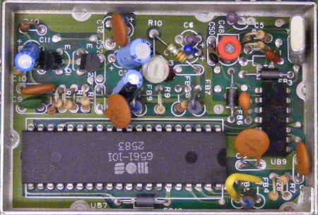
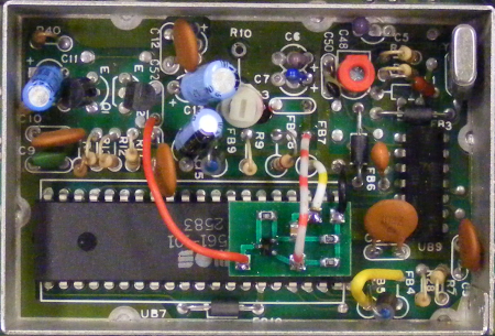
This is the video circuitry before and after the mod. FB7 and the 220 pF capacitor are removed. In place there's now a small board carrying a near exact copy of the luminance amplifying circuit. I used a BC817 SMD small-signal NPN transistor, and a 100 nF decoupling capacitor. The board gets the supply voltages over the red wire (+5V) and black wire (GND). Yellow-white: VIC Pin 2 (chroma) -> amplifier IN. Red-white: amplifier OUT -> mainboard. Note the transistor was soldered 'dead-bug' style, because the layout got mirrored by accident:
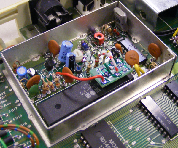
The small circuit board hovers a small distance over the VIC chip:
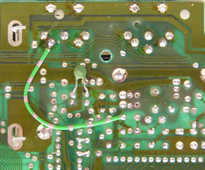
Finally, the chroma signal goes over the pink-green wire to pin 5 of Video Out. Note the trace cut between pins 4 and 5!
Here are screen details of a VFLI image before the mod (left) ... and after the mod (right):


Note how the teared pixels and white/black transients have gone away!
Greetings,
Michael


