Sometimes it's a good idea to breadboard a circuit first, ...
Posted: Sat Aug 29, 2020 8:07 am
... before making a PCB:
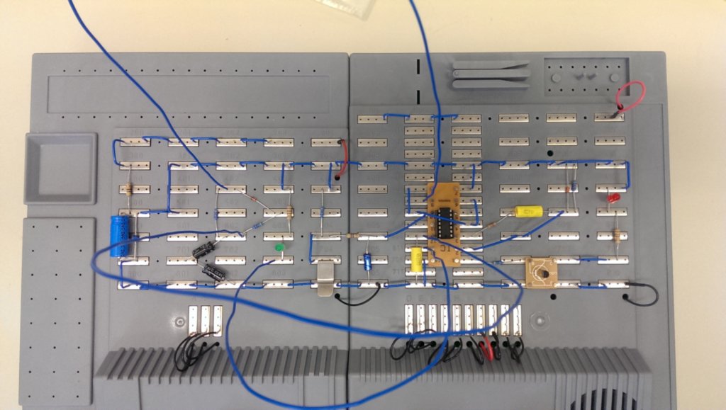
This circuit is supposed to provide a more versatile reset button for the MINIMON cartridge. A short press will result in a normal reset upon release, as expected. A long press (>1 second) will, upon button release, additionally inhibit BLK5 for a short duration (long enough to prevent the autostart of the slave cartridge), also the reset line going to the slave cartridge is temporarily opened: if the slave cartridge holds internal registers, they are kept across reset. This allows further analysis if these are for example banking registers.
Consequently, JP2 (the BLK5 inhibit jumper) will be removed from the next iteration of the MINIMON cartridge design. A blue SMD LED will signal the long button press to indicate this is going to be a 'freeze' reset.
The timings (button debounce, 2 ms reset pulse, 1 s freeze delay, 0.2 s BLK5 inhibit) are done with a 74HCT14 hex Schmitt trigger inverter and some RC networks. This seemed easy enough, however the first try led to an unexpected result:
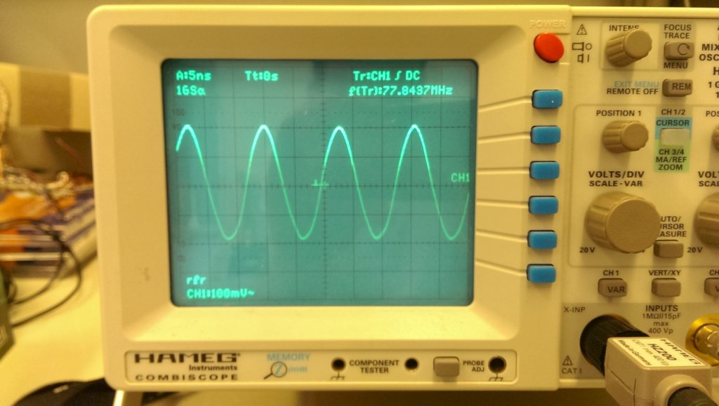
You surely don't want your VIC-20 to transmit RF at 78 MHz.
If you remove just one single component from the breadboard circuit shown above, you'll get this unwanted behaviour (hint: it's not the stabilizing capacitor for the 74HCT14 I missed out on the breadboard). Can you guess which one?
Greetings,
Michael
P.S. just as I wrote this, it occurred to me that the timing of the BLK5 inhibit would need a further refinement ...
This circuit is supposed to provide a more versatile reset button for the MINIMON cartridge. A short press will result in a normal reset upon release, as expected. A long press (>1 second) will, upon button release, additionally inhibit BLK5 for a short duration (long enough to prevent the autostart of the slave cartridge), also the reset line going to the slave cartridge is temporarily opened: if the slave cartridge holds internal registers, they are kept across reset. This allows further analysis if these are for example banking registers.
Consequently, JP2 (the BLK5 inhibit jumper) will be removed from the next iteration of the MINIMON cartridge design. A blue SMD LED will signal the long button press to indicate this is going to be a 'freeze' reset.
The timings (button debounce, 2 ms reset pulse, 1 s freeze delay, 0.2 s BLK5 inhibit) are done with a 74HCT14 hex Schmitt trigger inverter and some RC networks. This seemed easy enough, however the first try led to an unexpected result:
You surely don't want your VIC-20 to transmit RF at 78 MHz.
If you remove just one single component from the breadboard circuit shown above, you'll get this unwanted behaviour (hint: it's not the stabilizing capacitor for the 74HCT14 I missed out on the breadboard). Can you guess which one?
Greetings,
Michael
P.S. just as I wrote this, it occurred to me that the timing of the BLK5 inhibit would need a further refinement ...