Last weekend, acquired a crate of commodore stuff including a beautiful two-pin VIC-20. I've been cleaning and inspecting it, and when I got around to cleaning up the datasette, to my amazement it works! Loads original tapes! Except.. The motor never stops running. Traced the issue to the VIC-20 motherboard, two transistors Q4 and Q3. Someone had replaced them and bodged it badly. Missing pads and broken trace. Also noticed the transistors were EBC orientation. The schematic calls for EBC. The PCB is laid out for ECB!! I finally found a schematic that had ECB transistors, but it didn't match my assy number, and was wrong in other ways.
After I fixed all that, it didn't run at all. Turns out the zener diode CR1 had failed short circuit. Probably that was the original failure. The owner replaced the transistors with what the schematic says to use, and this appeared to work and they didn't notice or didn't care the motor was now latched on (it just freewheels unless the transport engages the tape when buttons are pressed.)
Has anyone noticed these errors in the schematics? Or do I have a strange board? It's screened as 324002-01 REV D
Datasette motor control snafu
Moderator: Moderators
-
Rmzalbar
- Vic 20 Newbie
- Posts: 8
- Joined: Fri Oct 11, 2019 2:29 am
- Location: San Diego
- Occupation: Programmer
Datasette motor control snafu
Last edited by Rmzalbar on Fri Oct 11, 2019 9:10 pm, edited 1 time in total.
-
eslapion

- ultimate expander
- Posts: 5458
- Joined: Fri Jun 23, 2006 7:50 pm
- Location: Canada
- Occupation: 8bit addict
Re: Datasette motor control snafu
I have never seen a schematic, VIC-20 or otherwise, which specifies the order of the pins of a BJT transistor. The datasheet has the final word.Rmzalbar wrote: ↑Fri Oct 11, 2019 2:48 am The schematic calls for EBC. The PCB is laid out for ECB!! I finally found a schematic that had ECB transistors, but it didn't match my assy number, and was wrong in other ways.
Has anyone noticed these errors in the schematics? Or do I have a strange board? It's screened as 324001-02
The symbol and pinout for a BJT transistor is: http://www.learnabout-electronics.org/S ... bjt_01.php
See fig 3.1.3
Be normal.
-
Rmzalbar
- Vic 20 Newbie
- Posts: 8
- Joined: Fri Oct 11, 2019 2:29 am
- Location: San Diego
- Occupation: Programmer
Re: Datasette motor control snafu
It is the part number of the transistor that determined the order of the legs. Japan style 2S vs 2N order. The schematic called for 2N3904 / 2N4401 transistors, after tracing the circuit found that the arrangement of pads on the board were for ECB, if you were to just install them per the silkscreen. Someone had put the former on there as a rework, with the base and collector switched. I removed them and put 2SC1815 in their place.
My board has a motor circuit matching this one - with 2N type transistors. Silkscreening of numbers identifying passives matches my board (R10, R11, etc.)
http://www.zimmers.net/anonftp/pub/cbm/ ... 01-02b.gif
However my PCB is in fact silkscreened and routed for the 2S type transistors in this schematic. However the numbering doesn't match my board (R20, R21, etc.)
http://www.zimmers.net/anonftp/pub/cbm/ ... 1027l2.gif
http://www.zimmers.net/anonftp/pub/cbm/ ... 1027r2.gif
My board doesn't seem to be accurately documented so far as I have found.. I should make an effort to get good photos of my PCB and identifying marks
OK, top of board:
ASSY NO. 324003
Underside:
FAB NO. 324002-01 REV.D
EDIT:
Replacing the transistors with 2S parts, replacing the zener diode, and repairing the broken trace restored normal tape motor operation. Happily loading old commercial tapes, as well as tapes restored from .TAP files written back to tape by my 1541 U2+
EDIT 2:
The interesting thing about the figure you pointed me to is that it showed the ECB pin order as a TO-94. However, the 2SC1815 I used are definitely TO-92 package per the datasheet, but the TO-94 packages I find are all four-pin. I am more confused.
-
Rmzalbar
- Vic 20 Newbie
- Posts: 8
- Joined: Fri Oct 11, 2019 2:29 am
- Location: San Diego
- Occupation: Programmer
Re: Datasette motor control snafu
I flipped through my VIC-20 books, and in one of them, found a fold-out schematic that matches my board! I haven't seen this particular version elsewhere on the web. I want to scan it and make it available. Where should I submit it to?
-
joshuadenmark

- Big Mover
- Posts: 1218
- Joined: Sat Oct 23, 2010 11:32 am
- Location: Fr-Havn, Denmark
- Occupation: Service engineer
Re: Datasette motor control snafu
Submit it as many sites as possible.
You are most welcome to Submit it here too.
You are most welcome to Submit it here too.
Kind regards, Peter.
____________________________________________________
In need of a wiki logon - PM me
____________________________________________________
In need of a wiki logon - PM me
-
eslapion
- ultimate expander
- Posts: 5458
- Joined: Fri Jun 23, 2006 7:50 pm
- Location: Canada
- Occupation: 8bit addict
Re: Datasette motor control snafu
In 2016, I scanned schematics 324001-02 and sent them to Zimmers for online posting.
Page 1: http://www.zimmers.net/anonftp/pub/cbm/ ... 01-02a.gif
Page 2: http://www.zimmers.net/anonftp/pub/cbm/ ... 01-02b.gif
Page 3: http://www.zimmers.net/anonftp/pub/cbm/ ... 01-02c.gif
It's a good thing I did as the book which contained them was destroyed in November 2018.
You indicated you have 324002 and I suspect it's just the PAL version of the same.
Since you refer above to both the scans I posted and other schematics which are related to the VIC-20cr, I have to ask: Does your VIC-20 have a 2 prong power supply connector or does it use the round 7 pin DIN connector ?
Can you take a high quality photo of your board ?
Be normal.
-
Rmzalbar
- Vic 20 Newbie
- Posts: 8
- Joined: Fri Oct 11, 2019 2:29 am
- Location: San Diego
- Occupation: Programmer
Re: Datasette motor control snafu
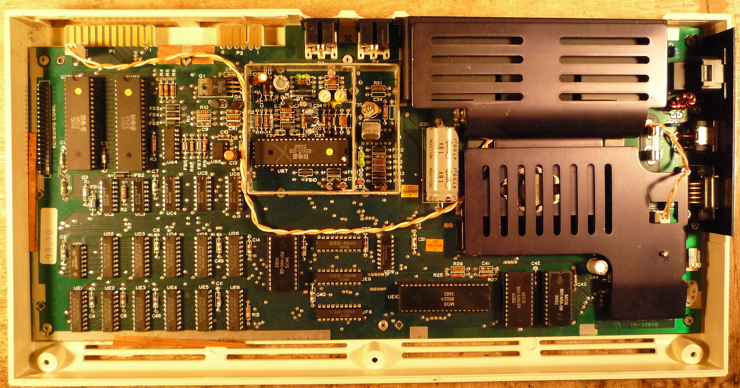
It is 2-prong, NTSC, with a two-compartment RF box.
Here are the photos I took last time I had it out:
https://photos.app.goo.gl/jWjd287HtowLS2Vw9
Not exactly archival grade - I will take another series with this in mind soon when I open it up to repair a stripped thread. One of the photos is a close-up of the power delivery circuit for the cassette motor. The soldering doesn't look good on that side because of the missing pads. Also I was still waiting for a replacement zener which I had already removed.
I'll scan the schematic tonight as well.
-
eslapion
- ultimate expander
- Posts: 5458
- Joined: Fri Jun 23, 2006 7:50 pm
- Location: Canada
- Occupation: 8bit addict
Re: Datasette motor control snafu
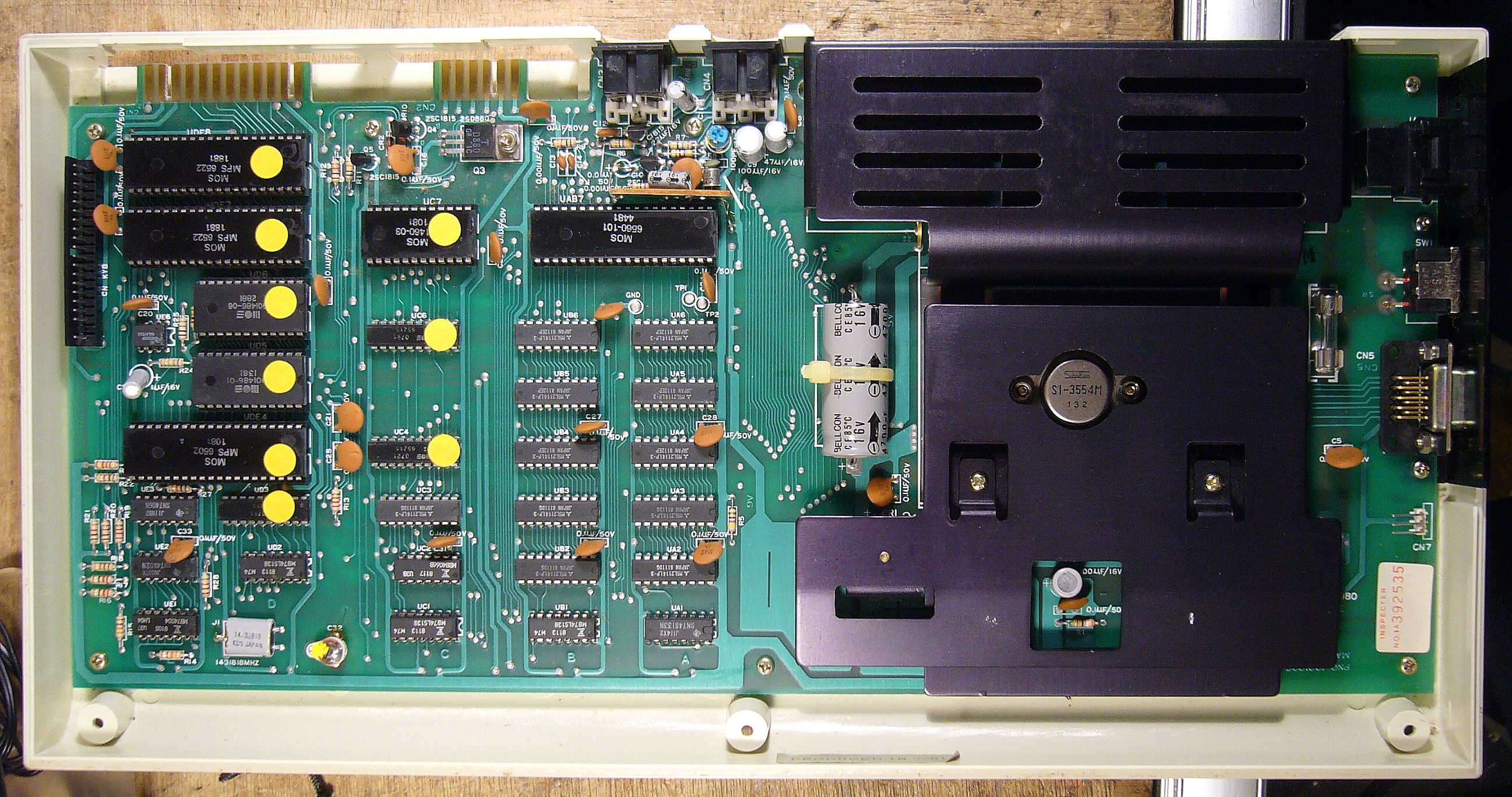
You're in luck, the mainboard of my VIC-20 with PET style keyboard is identical to yours. The actual number etched on the lower right corner is 324003 and that's the first VIC-20 board which was made in USA. It sold from late 1981 to summer 1982.Rmzalbar wrote: ↑Sun Oct 20, 2019 6:40 pm It is 2-prong, NTSC, with a two-compartment RF box.
Here are the photos I took last time I had it out:
https://photos.app.goo.gl/jWjd287HtowLS2Vw9
Not exactly archival grade - I will take another series with this in mind soon when I open it up to repair a stripped thread. One of the photos is a close-up of the power delivery circuit for the cassette motor. The soldering doesn't look good on that side because of the missing pads. Also I was still waiting for a replacement zener which I had already removed.
I'll scan the schematic tonight as well.
It's very similar to schematics 324001 but there are a few differences and this includes the power control of the datassette. The original plan (used on early 'Made in Japan' boards, identical to those of the VIC-1001) required 3 BJTs, 2 of which are in a Darlington configuration and required a Zener diode of 7.5V. That's what you seen in schematic 324001.
On board 324003, (your and mine), the datassette power control uses 2 BJTs (a 2SC1815 and a 2SD880 - Q3 and Q4) and a Zener diode of 6.8V. This configuration is identical to what you see in the VIC-20cr schmatic 251027.
Here: (the datassette power control is split in both of these images)
http://www.zimmers.net/anonftp/pub/cbm/ ... 1027l2.gif
http://www.zimmers.net/anonftp/pub/cbm/ ... 1027r2.gif
This is what you and I have:
https://upload.wikimedia.org/wikipedia/ ... nboard.JPG or https://myoldcomputer.nl/wp-content/upl ... 324003.jpg
This is the actual 324001 used on the earliest VIC-20s and the VIC-1001: https://myoldcomputer.nl/wp-content/upl ... ic20-E.jpg
Even on that board Q4 was replaced with a 2SC1815 and to avoid pin configuration errors, it's indicated on the board.
You want to see a VIC-20 which uses the 2N transistors ? Look here... check the 6522 datecodes !!! http://sleepingelephant.com/ipw-web/bul ... php?t=9088
Be normal.
-
Rmzalbar
- Vic 20 Newbie
- Posts: 8
- Joined: Fri Oct 11, 2019 2:29 am
- Location: San Diego
- Occupation: Programmer
Re: Datasette motor control snafu
Mine has the most common C64-breadbin-style keyboard with the medium-brown function keys. I do wish it had the PET keyboard, they look so good. We had a PET in the corner of many of my 1st-5th gradeschool classrooms that nobody ever touched except for me.
I have a schematic on my lap that shows three BJT's, two in darlington, but 2 are SC and 1 is SD, with a 7.5v zener. This is matching my board. The schematic is dated 1980. You can see there are three transistors involved in my photos. So I have an uncommon variant, perhaps..
I meant to scan it last night but got sidetracked resurrecting a 1950 monitor (with an 8-inch crack in its power supply PCB!!) I'm all out of broken CRTs, so time to hit the scanner.
EDIT: Here it is.
PNG format:
https://drive.google.com/open?id=17-bo6 ... Y3pj6rZSa1
https://drive.google.com/open?id=1NYome ... zjQXDqe7YX
https://drive.google.com/open?id=1Dbc7X ... IT-DPu53wH
https://drive.google.com/open?id=1nf3Cp ... RjJQPok7Yg
PDF, if you like that sort of thing:
https://drive.google.com/open?id=14xMox ... wbbTqmwd4J
The book this came from is,
VIC-20 Programmer's Reference Guide
A. Finkel
N. Harris
P. Higgenbottom
M. Tomczyk
Copyright 1982
Commodore Computer
Distributed by Commodore Business Machines (U.K.) Ltd.
ISBN: 0-672-21948-4
-
eslapion
- ultimate expander
- Posts: 5458
- Joined: Fri Jun 23, 2006 7:50 pm
- Location: Canada
- Occupation: 8bit addict
Re: Datasette motor control snafu
Yeah, the schematics from the PRG was also posted on Zimmer's but, for reasons I cannot fathom, it's in TIFF format.
The datassette motor control with the Darlington config only wastes 0.08W of power when inactive, unlike the one used on later generations of C64 which waste 0.3W of power and require a 0.5W resistor on the base of the large BJT.
Be normal.
-
Rmzalbar
- Vic 20 Newbie
- Posts: 8
- Joined: Fri Oct 11, 2019 2:29 am
- Location: San Diego
- Occupation: Programmer
Re: Datasette motor control snafu
My gosh, there it is at the bottom of the page! I don't know how I missed it. Well, I think my scans are better quality at any rate.