Page 1 of 2
My 2-prong DC PSU experiments
Posted: Thu May 05, 2016 1:19 am
by Boray
In 2004 I had the idea of using a DC power supply with the 9V Vic-20:
http://sleepingelephant.com/ipw-web/bul ... 7&start=23
Now when Oge_user is offering a 12.4 VDC PSU as a replacement PSU for the 9V Vic-20, I made some test...
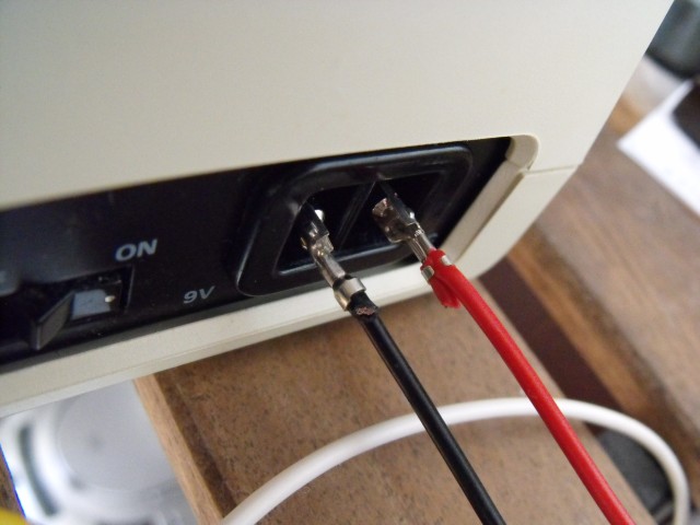
I found this one in the basement:
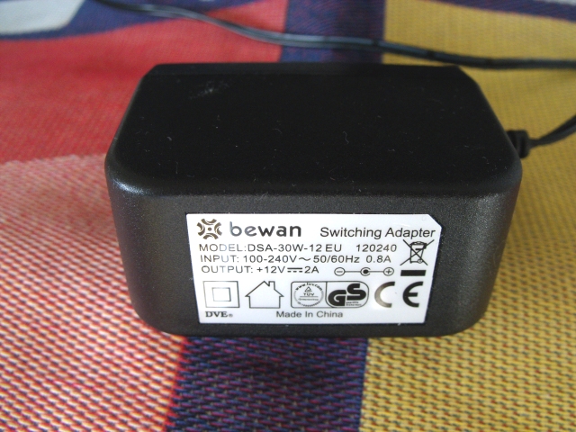
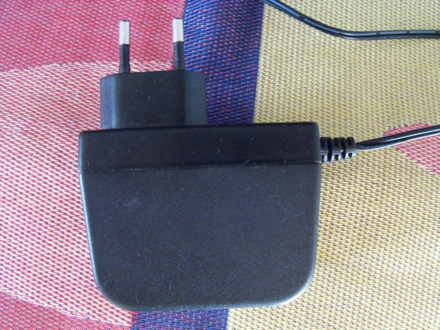
...and "plugged it in":
Measuring the heat as well:
Using a multimeter and comparing it to the original, the Vic-20 CR and another 12V PSU, I got the following:
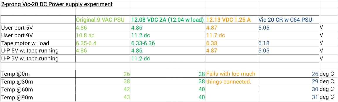
As you can see, this 12.08 VDC supply gives the same levels inside the vic-20 as the original PSU (as long as you don't plan to use that 9v AC on the user port, but who does???) The tape worked perfectly by the way.
The test also indicates that the 12 V DC makes the vic-20 run at a slightly lower temperature. I'ts no radical difference though. It's still an oven compared to the vic20CR.
If you want the tape to work properly, my guess is that you need 12 V or it could work with slightly less (like 11,5) but that is guessing.
I would like to try something like 8-10 V DC to see how that works some day. (Because lower V should mean lower temperature). Maybe it takes me another 12 years to find one delivering 2A in the trash though... (12.4V as oge is offering seems a bit unneccesary high to me).
The 1.25 A 12.13 V PSU in the test worked as long as I didn't plug in the expansion port expander. So you clearly need more amps than that. A strange thing with that PSU though: It bypassed the power switch! Then I changed polarity and the power switch worked.
I also tried 5V from a PC PSU. Nothing happened.
Another interesting result is that the vic-20 CR's 5V is about 4% higher than in the old vic. Which is better for the chips, running them at a lower voltage or running them in a lower temperature environment?
Re: My 2-prong DC PSU experiments
Posted: Fri May 06, 2016 4:00 am
by eslapion
If you're willing to push this experiment a step further, you could use a 5V/12V PSU such as those provided with external USB2/USB3 hard drives.
Remove the 5V regulator inside the VIC-20 and plug the 5Vdc to the output line of the regulator and you'll have a nice "no heat" machine.
Re: My 2-prong DC PSU experiments
Posted: Mon Jun 13, 2016 10:27 am
by Boray
*** PART 2 ***
In the name of science (well, hmmm...) I went on and bought this 9V DC 3A PSU:
https://www.kjell.com/se/sortiment/el-v ... 7-w-p44716
It works, and the Vic-20 runs cooler. Here is a table of the voltages compared to the others:
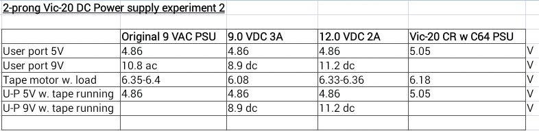
The tape works perfectly. I even tried the pulse game tape and it worked.
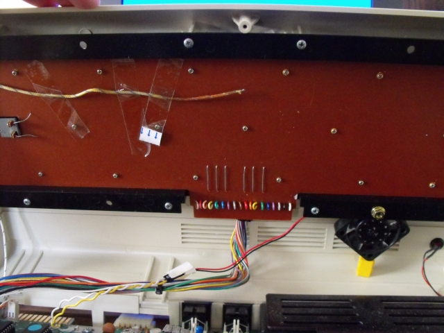
Now, how much of a difference is there in the temperature? I measured at two different positions:
In this presentation, I call this one position M (M for motherboard):
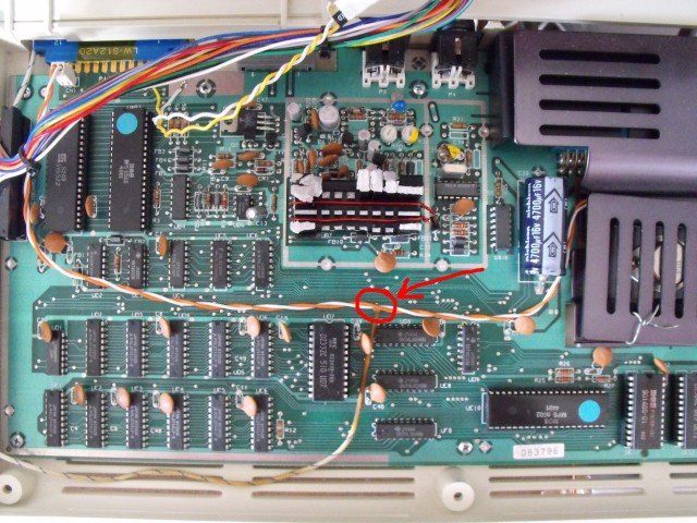
And this one I call position K (for keyboard):
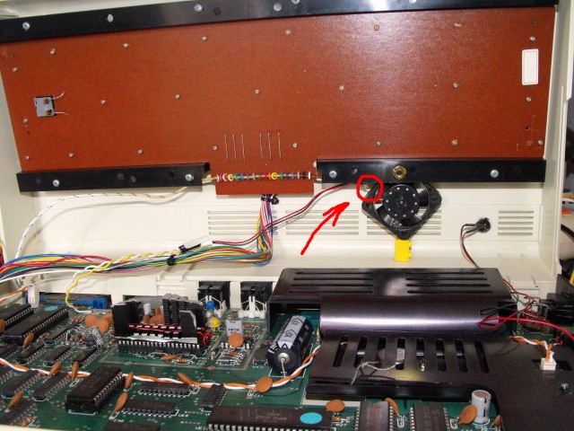
(Note: the fan was disconnected)
I then measured with the original 9V AC psu, the 12 V DC psu and the new 9V DC psu until the temperatures got stabilized and got these temperatures:
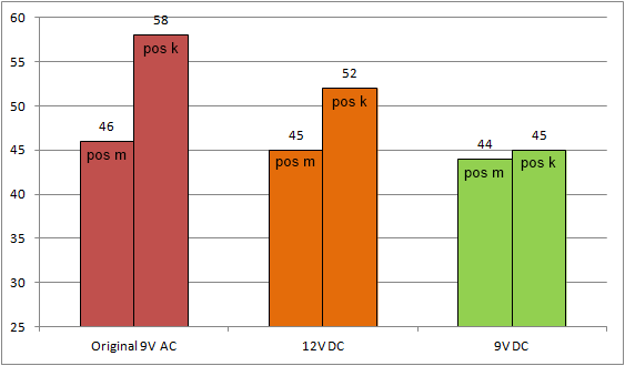
This is in degrees Celcius. For those of you not familiar with this scale, 0 = freezing point for water, 100 = boiling point for water, 20-25 = normal indoor temperature.
As you can see, the motherboard temperature does not differ very much at position M. The position K temperature does!
So, the motherboard temperature would probably indicate that using a 9V DC psu instead of the original AC isn't of any great importance for the wear and tear of the chips inside. Note however that I've removed the cardboard inside the computer. The computer is also standing on a splint table allowing for fresh air to come directly into the computer from below. I expect the temperature differences to be much bigger on an unmodded computer standing on a normal table.
There are also chips closer to the rectifier and power regulator that maybe will benefit from lower temperatures.
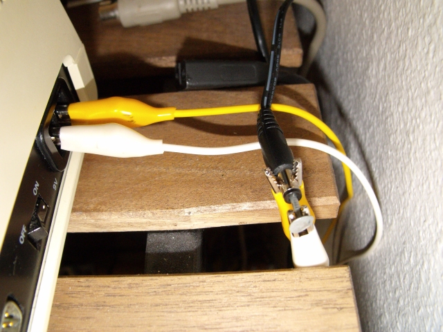
The crocodile clamps I used with the 12V psu wasn't enough for the 9V DC. The colors of the display momentarily disappeared when pressing play. So, instead, I made these connectors:
...which I took from this one:
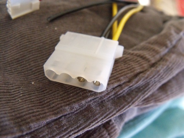
...and bent open a great deal. I think something bigger probably is better. This works though.
Re: My 2-prong DC PSU experiments
Posted: Mon Jun 13, 2016 4:23 pm
by Oge_user
Very informative thread; I'm currently reading the results of your tests and comparing these to mine. The temperature may be slightly lower comparing 9VAC to 12VDC but the benefits for the regulator (for the simple fact that we are feeding it with regulated DC instead of unregulated DC) are surely important.
I will add some informations which will be useful for other forum members:
- 12VDC@3,0A is the recommended amperage;
- 12VDC@3,6A~3,8A is the ideal one in case of VIC equipped with power-hungry expansions;
- Voltages lower than 12VDC are indeed possible (10/9VDC) but in such cases I would use a Power Supply with no less than 3A (the one offered on Marketplace have 4A just to stay perfect)
And, last but not least:
- You can TRY 8VDC (minimum dropout voltage required for the internal voltage regulator) but I have not tested that;
- You can clean-up incoming DC voltage (using EMI filters, ferrite cores and additional capacitors) for the purpose of easening the life of the internal voltage regulator.
Too bad the 2-Prong connector is not only *particular* but changes from model to model.
I am also trying to find a way to feed DC to C64 instead of 9VAC without touching the motherboard itself but there are charge pumpers prior to the 7812 which powers the SID and other particularities which makes this a difficult task.
Cheers,
Oge
Re: My 2-prong DC PSU experiments
Posted: Mon Jun 13, 2016 4:31 pm
by Oge_user
By the way: tape motor greatly benefits from using DC instead of AC as a source for its final voltage.
I've seen that on Datassettes connected to PC for dumping of tapes: Datassette clones seems to work slightly better with VDC instead of VCC... Of course this applies to 1530/1531 C2Ns as well but on clones, which are cheaper, this is more evident.
Of course, it is important to use a very clean source for DC: cheap Switching Power Supplies are not good enough and the ideal goal is to combine several factors and get as much lifespan out of a Commodore as possible.

Cheers,
Oge
Re: My 2-prong DC PSU experiments
Posted: Thu Jun 16, 2016 4:39 am
by e5frog
It would be kind of odd if it wasn't cooler by the graetz bridge when running DC there - but if running DC,why keep it at all, it's of no use and you'd save two warm diodes.
Re: My 2-prong DC PSU experiments
Posted: Thu Jun 16, 2016 7:17 am
by Oge_user
Keeping the motherboard untouched is a strong point, I wouldn't remove nor alter anything on the VIC board.
Finding a different connector which, by luck, fits perfectly the larger 2-Prong VIC would be cool.
Re: My 2-prong DC PSU experiments
Posted: Thu Jun 16, 2016 10:06 am
by Boray
Connecting a new PSU (that even doesn't need a special polarity) is an easy task most people can do. Removing parts of the motherboard is something most people can't or don't want to do.
I wonder if Commodore designed it with different powering alternatives in mind. You should be able to run it on a normal car battery for example.
Re: My 2-prong DC PSU experiments
Posted: Mon Jul 31, 2017 8:31 am
by Boray
I just measured the userport 5v on a vic20cr with a c128 psu (with adapted connector). It was 4.87 v, just as on the non-cr vic-20.
Re: My 2-prong DC PSU experiments
Posted: Mon Jul 31, 2017 9:56 am
by mrr19121970
Did you see this too ?
http://sleepingelephant.com/ipw-web/bul ... =11&t=8479
We also had a discussion on bringing 9vAC into the user port, like the Arfon expander too
http://sleepingelephant.com/ipw-web/bul ... fon#p86970
Re: My 2-prong DC PSU experiments
Posted: Sun Aug 06, 2017 6:10 am
by pms
Thanks for all the interesting info in this thread!
I tried a 9v AC 30 watts transformer to get my 2 prong Vic working but was not satisfied with the result on my old Vic.
The screen showes dark horizontal parts on the screen.
These dark parts slowly move in a vertical direction.
Found this thread
so I tried a 12 volt AC adapter: the dark parts disappeared.
(it is difficult to get on a photo but I tried)
Re: My 2-prong DC PSU experiments
Posted: Sun Aug 06, 2017 10:03 am
by e5frog
Maybe you have bad capacitor(s) that cause too much ripple...
Re: My 2-prong DC PSU experiments
Posted: Sun Aug 06, 2017 10:06 am
by Boray
pms wrote:Thanks for all the interesting info in this thread!
I tried a 9v AC 30 watts transformer to get my 2 prong Vic working but was not satisfied with the result on my old Vic.
The screen showes dark horizontal parts on the screen.
These dark parts slowly move in a vertical direction.
Found this thread
so I tried a 12 volt AC adapter: the dark parts disappeared.
(it is difficult to get on a photo but I tried)
But 12 V AC? That is too much!!!
I think your rectifier bridge is bad or has bad solders. Doesn't your fuse blow? I got a similar effect on the screen with a bad rectifier, until the fuse blew.
And why do you have a few bytes too much of memory?
Re: My 2-prong DC PSU experiments
Posted: Sun Aug 06, 2017 10:10 am
by e5frog
I'd guess he means an AC-DC adapter, giving 12VDC...?
3628 bytes memory is a bit odd... maybe there are more than one problem on this one.
Re: My 2-prong DC PSU experiments
Posted: Mon Aug 07, 2017 12:38 am
by pms
The 12 volt AC adapter I am using is a real 12 volt AC adapter
When I turn on the VIC the output drops to 9,2 volt.
I tested the voltage from the LM325:
- using the 9 volt AC adapter it supplies 4,3 volt and bad image
- using the 12 volt AC adapter it supplies 4,9 volt and the image is much better.
I also noticed the rectifier bridge and 4 memory chips have been replaced in the past

So this is going to be a nice "winter" project for me I suppose