So, DQH recently started adding support for proper interlaced rendering (right now works with C128 VDC only) - so i'd like to add support for this in xvic aswell. Unfortunately i couldnt find any detail info on how it actually works, perhaps one of you (tokra?) can shed some light on it
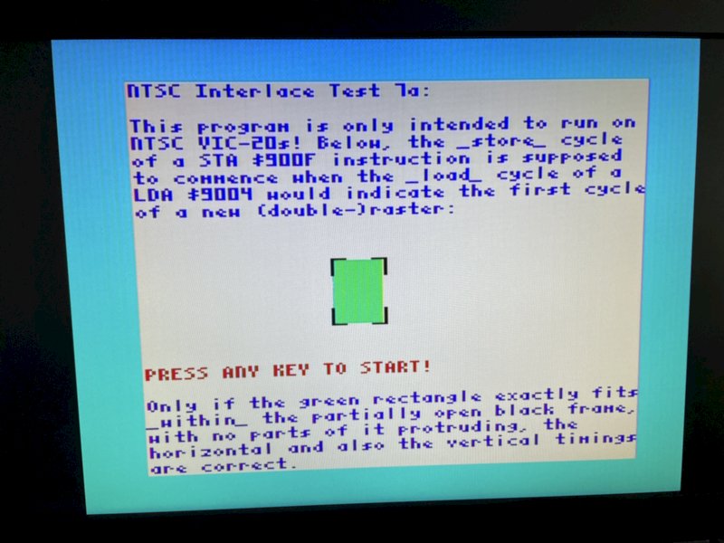
first, is it correct that the general idea is to set bit 7 in $9000 and then the VIC shows alternating frames with "half a line" offset every other frame. it doesnt handle any page flipping or whatever else by itself. and the only way to find out what field is (has been) displayed is by checking the presence of rasterline 263 ($83 in the register)?
then, i need to know precisely how many cycles are spent in the last rasterline of odd and even frames - this is the key to get timing right.
It would be really nice if someone who owns a NTSC vic20 could knock up some simple test programs that checks those things, so we can make it work in VICE
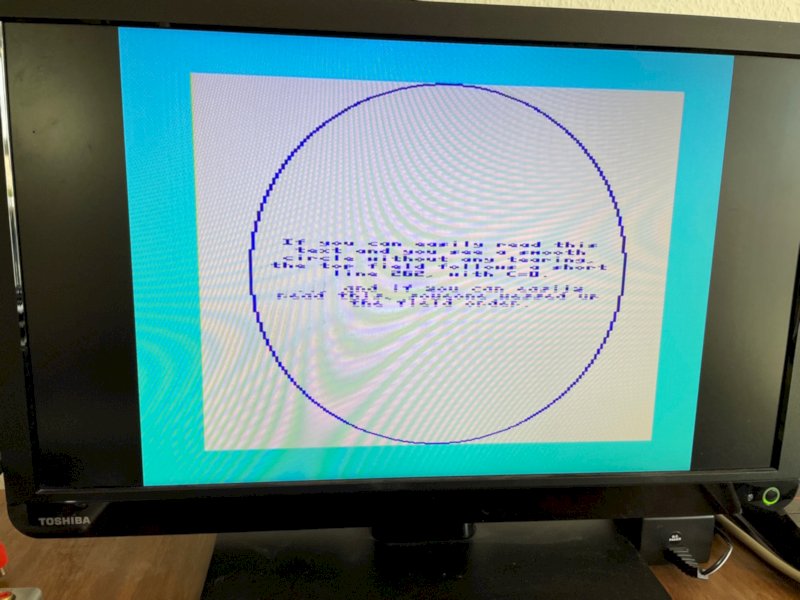
I tried using "retina display" and actually managed to make it show something by simple alternating between 262 and 263 lines in odd/even fields, however, although the display is stable (the raster splits do not crawl over the picture, so the overall amount of cycles is spot on) they are not at the right places, which makes me believe there isnt actually a full line 262 and/or 263 - which actually makes sense.
here is my current hack, very ugly (and also makes bit7 work on PAL, it will likely totally misbehave in that case) is here: http://dpaste.com/8SLXWJC6B - i couldnt work it out yet by trial and error, so its probably not quite right
Speak up please!