A Happy New Year to all!

For this post, the download link goes first - without further ado:
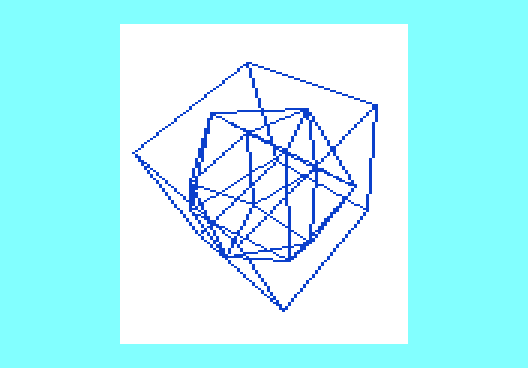
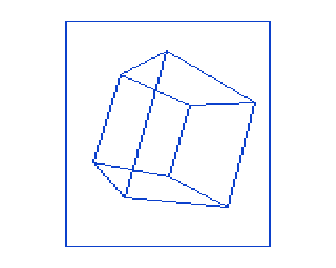
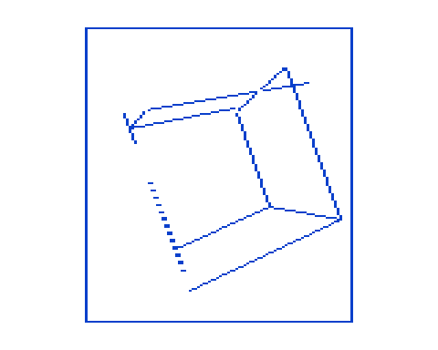
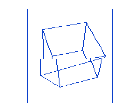
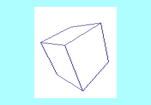
blended.zip. Uncompress the archive and run the file BOOT with at least a +8K RAM expansion. You see the cube rotator using
blended code: the geometry engine is now completely written in machine code, the graphics part still uses MINIGRAFIK as test rig for the machine code.
It now runs at
2 fps.

Now for the longer part: as already mentioned in the post about the multiply routine, the multiply routine is intended to be inlined into the geometry engine to avoid redundant memory/'register' transfers. Before we go about that, at first we need to identify all relevant temporaries, these are:
- zp_ax, zp_ay, zp_az: 3 angles for each axis, 1 byte each,
- zp_vertex: index for running vertex number, values 0..7,
- zp_x1, zp_y1, zp_z1: the first set of co-ordinate temporaries, 1 byte each, 2:6 fixpoint,
- zp_x2, zp_y2, zp_z2: the second set of co-ordinate temporaries, 1 byte each, 2:6 fixpoint,
- zp_sin, zp_P: sine of angle or horizontal reciprocal, 1 byte, 2:6 fixpoint,
- zp_cos, zp_Q: cosine of angle or vertical reciprocal, 1 byte, 2:6 fixpoint,
- zp_temp1: first product in rotation sum/difference, or horizontal projection temporary, 2 bytes, 4:12 fixpoint,
- zp_temp2: second product in rotation sum/difference, or vertical projection temporary, 2 bytes, 4:12 fixpoint,
- zp_temp: 1 byte temporary value, used during the projection step.
We are going to put all these in Zeropage. For the moment, zp_ax, zp_ay and zp_az are placed in $03..$05, the others go to addresses
$58..$65. This is the storage used by the BASIC interpreter to hold float values during calculations - we just decided to let a machine code routine do that job, so the interpreter won't complain.

The angle values will join their peers at $55..$57 in a later version that is the full machine code version, but in the moment they are input parameters from BASIC and need to be stored at free addresses.
We will place the arrays for the X, Y, Z input vertex values in protected BASIC RAM, as well as the arrays for the resulting U and V output screen co-ordinates.
It would be quite daring to convert the whole program to machine code in one step! First, the geometry engine has to be right. That means: there are the loop control instructions, 6 sine/cosine table lookups, 12 slightly different multiplies (written out), 6 sum/differences with conversions from 4:12 to 2:6 fixpoint, 2 reciprocal lookups, another 2 customized multiplies and another 2 conversions 4:12 -> 2:6 fixpoint for the projection and finally outputting the screen co-ordinates. Especially the multiplies could become a big bag of bugs, if we'd go and instantiate them by changing all parameter zp addresses manually!
We use a
template generator instead, written in C:
Code: Select all
/*
 *  geometry.c - emit a 65xx 3D geometry engine from template/macro definitions
 *
 *  written 2025-01-02 by Michael Kircher
 *
 *  - this results in raw source code, the resulting output will need its labels
 *    to be unified as "Geometry_XX", and have boilerplate added for assembler.
 */

#include <stdio.h>
#include <stdlib.h>

void expand0(FILE *stream,
             char *angle)
{
  fprintf(stream," LDX %s\n",angle);
  fprintf(stream," LDA abs_SIN,X   :STA zp_sin\n");
  fprintf(stream," LDA abs_SIN+64,X:STA zp_cos\n");
  fprintf(stream,"\n");
}

void expand1(FILE *stream,
             char *factor_1, char *factor_2,
             char *result_lo, char *result_hi,
             char *label)
{
  fprintf(stream," SEC:LDA %s:SBC %s:BCS %s_00:EOR #255:ADC #1\n",factor_1,factor_2,label);
  fprintf(stream,".%s_00\n",label);
  fprintf(stream," TAY:CLC:LDA %s:ADC %s:TAX:BCC %s_01\n",factor_1,factor_2,label);
  fprintf(stream," LDA abs_SQ_Lo+256,X:SBC abs_SQ_Lo,Y:STA %s\n",result_lo);
  fprintf(stream," LDA abs_SQ_Hi+256,X:SBC abs_SQ_Hi,Y:BCS %s_02\n",label);
  fprintf(stream,".%s_01\n",label);
  fprintf(stream," SEC\n");
  fprintf(stream," LDA abs_SQ_Lo,X:SBC abs_SQ_Lo,Y:STA %s\n",result_lo);
  fprintf(stream," LDA abs_SQ_Hi,X:SBC abs_SQ_Hi,Y\n");
  fprintf(stream,".%s_02\n",label);
  fprintf(stream," BIT %s:BPL %s_03:SBC %s\n",factor_1,label,factor_2);
  fprintf(stream,".%s_03\n",label);
  fprintf(stream," BIT %s:BPL %s_04:SEC:SBC %s\n",factor_2,label,factor_1);
  fprintf(stream,".%s_04\n",label);
  fprintf(stream," STA %s\n",result_hi);
  fprintf(stream,"\n");
}

void expand2(FILE *stream,
             char *result)
{
  fprintf(stream," SEC\n");
  fprintf(stream," LDA zp_temp1:SBC zp_temp2:STA zp_temp\n");
  fprintf(stream," LDA zp_temp1+1:SBC zp_temp2+1\n");
  fprintf(stream," ASL zp_temp:ROL A\n");
  fprintf(stream," ASL zp_temp:ROL A\n");
  fprintf(stream," ASL zp_temp:ADC #0\n");
  fprintf(stream," STA %s\n",result);
  fprintf(stream,"\n");
}

void expand3(FILE *stream,
             char *result)
{
  fprintf(stream," CLC\n");
  fprintf(stream," LDA zp_temp1:ADC zp_temp2:STA zp_temp\n");
  fprintf(stream," LDA zp_temp1+1:ADC zp_temp2+1\n");
  fprintf(stream," ASL zp_temp:ROL A\n");
  fprintf(stream," ASL zp_temp:ROL A\n");
  fprintf(stream," ASL zp_temp:ADC #0\n");
  fprintf(stream," STA %s\n",result);
  fprintf(stream,"\n");
}

int main(int argc, char *argv[])
{
  FILE *stream;
  if(NULL == (stream = fopen("source.00.txt","wt"))) exit(EXIT_FAILURE);


  /* ** start of loop, load vertex values into temporaries */
  fprintf(stream,".Geometry\n");
  fprintf(stream," LDX #0\n");
  fprintf(stream,".Geometry_00\n");
  fprintf(stream," STX zp_vertex\n");
  fprintf(stream," LDA abs_X,X:STA zp_x1\n");
  fprintf(stream," LDA abs_Y,X:STA zp_y1\n");
  fprintf(stream," LDA abs_Z,X:STA zp_z1\n");
  fprintf(stream,"\n");

  /* ** rotate around all 3 axes */
  expand0(stream,"zp_ax");

  expand1(stream,"zp_cos","zp_y1","zp_temp1","zp_temp1+1","Multiply_01");
  expand1(stream,"zp_sin","zp_z1","zp_temp2","zp_temp2+1","Multiply_02");
  expand2(stream,"zp_y2");

  expand1(stream,"zp_sin","zp_y1","zp_temp1","zp_temp1+1","Multiply_03");
  expand1(stream,"zp_cos","zp_z1","zp_temp2","zp_temp2+1","Multiply_04");
  expand3(stream,"zp_z2");

  expand0(stream,"zp_ay");

  expand1(stream,"zp_cos","zp_z2","zp_temp1","zp_temp1+1","Multiply_05");
  expand1(stream,"zp_sin","zp_x1","zp_temp2","zp_temp2+1","Multiply_06");
  expand2(stream,"zp_z1");

  expand1(stream,"zp_sin","zp_z2","zp_temp1","zp_temp1+1","Multiply_07");
  expand1(stream,"zp_cos","zp_x1","zp_temp2","zp_temp2+1","Multiply_08");
  expand3(stream,"zp_x2");

  expand0(stream,"zp_az");

  expand1(stream,"zp_cos","zp_x2","zp_temp1","zp_temp1+1","Multiply_09");
  expand1(stream,"zp_sin","zp_y2","zp_temp2","zp_temp2+1","Multiply_10");
  expand2(stream,"zp_x1");

  expand1(stream,"zp_sin","zp_x2","zp_temp1","zp_temp1+1","Multiply_11");
  expand1(stream,"zp_cos","zp_y2","zp_temp2","zp_temp2+1","Multiply_12");
  expand3(stream,"zp_y1");

  /* ** project and store resulting screen co-ordinates */
  fprintf(stream,".Geometry_xx\n");
  fprintf(stream," LDX zp_y1\n");
  fprintf(stream," LDA abs_P,X:STA zp_P\n"); /* zp_P: same adr. as zp_sin */
  fprintf(stream," LDA abs_Q,X:STA zp_Q\n"); /* zp_Q: same adr. as zp_cos */
  fprintf(stream,"\n");

  expand1(stream,"zp_x1","zp_P","zp_temp1","zp_temp1+1","Multiply_13");

  fprintf(stream," LDX zp_vertex\n");
  fprintf(stream," LDA zp_temp1+1\n"); /* peephole against STA zp_temp1+1 in Multiply_13! */
  fprintf(stream," ASL zp_temp1:ROL A\n");
  fprintf(stream," ASL zp_temp1:ROL A\n");
  fprintf(stream," ASL zp_temp1:ADC #48:STA abs_U,X\n");
  fprintf(stream,"\n");

  expand1(stream,"zp_z1","zp_Q","zp_temp2","zp_temp2+1","Multiply_14");

  fprintf(stream," LDX zp_vertex\n");
  fprintf(stream," LDA zp_temp2+1\n"); /* peephole against STA zp_temp2+1 in Multiply_14! */
  fprintf(stream," ASL zp_temp2:ROL A\n");
  fprintf(stream," ASL zp_temp2:ROL A\n");
  fprintf(stream," ASL zp_temp2:ADC #0:STA zp_temp\n");
  fprintf(stream," SEC:LDA #80:SBC zp_temp:STA abs_V,X\n");
  fprintf(stream,"\n");

  /* ** end of loop */
  fprintf(stream," INX\n");
  fprintf(stream," CPX #8\n");
  fprintf(stream," BEQ Geometry_zz\n");
  fprintf(stream," JMP Geometry_00\n");
  fprintf(stream,".Geometry_zz\n");
  fprintf(stream," RTS\n");

  fclose(stream);

  exit(EXIT_SUCCESS);
}
You see there is a section "** rotate around all 3 axes" - take the time and compare it with lines 30..32 of the cube rotator in the Dec 30th post. Each of the original BASIC statements finds a counterpart in the macro/template expansion process!
The emitted, "raw" assembly code then has its labels unified with the "Geometry_XX" naming scheme and also boilerplate added to support the actual assembly, here's the result:
Code: Select all
REM>geometry
:
zp_ax = &03:REM ** -> &55
zp_ay = &04:REM ** -> &56
zp_az = &05:REM ** -> &57
zp_vertex = &58
zp_x1 = &59
zp_y1 = &5A
zp_z1 = &5B
zp_x2 = &5C
zp_y2 = &5D
zp_z2 = &5E
zp_sin = &5F:zp_P = &5F
zp_cos = &60:zp_Q = &60
zp_temp1 = &61:REM ** 16 bit
zp_temp2 = &63:REM ** 16 bit
zp_temp = &65
:
abs_X = &3300
abs_Y = &3300 +  32
abs_Z = &3300 +  64
abs_U = &3300 +  96
abs_V = &3300 + 128
:
abs_SQ_Lo = &3400
abs_SQ_Hi = &3600
abs_P = &3800
abs_Q = &3900
abs_SIN = &3A00
:
DIM code 4096
:
FOR pass=4 TO 7 STEP 3
P%=&3B65-2:O%=code
[OPT pass
 EQUW P%+2

.Geometry
 LDX #0
.Geometry_00
 STX zp_vertex
 LDA abs_X,X:STA zp_x1
 LDA abs_Y,X:STA zp_y1
 LDA abs_Z,X:STA zp_z1

 LDX zp_ax
 LDA abs_SIN,X   :STA zp_sin
 LDA abs_SIN+64,X:STA zp_cos

 SEC:LDA zp_cos:SBC zp_y1:BCS Geometry_01:EOR #255:ADC #1
.Geometry_01
 TAY:CLC:LDA zp_cos:ADC zp_y1:TAX:BCC Geometry_02
 LDA abs_SQ_Lo+256,X:SBC abs_SQ_Lo,Y:STA zp_temp1
 LDA abs_SQ_Hi+256,X:SBC abs_SQ_Hi,Y:BCS Geometry_03
.Geometry_02
 SEC
 LDA abs_SQ_Lo,X:SBC abs_SQ_Lo,Y:STA zp_temp1
 LDA abs_SQ_Hi,X:SBC abs_SQ_Hi,Y
.Geometry_03
 BIT zp_cos:BPL Geometry_04:SBC zp_y1
.Geometry_04
 BIT zp_y1:BPL Geometry_05:SEC:SBC zp_cos
.Geometry_05
 STA zp_temp1+1

 SEC:LDA zp_sin:SBC zp_z1:BCS Geometry_06:EOR #255:ADC #1
.Geometry_06
 TAY:CLC:LDA zp_sin:ADC zp_z1:TAX:BCC Geometry_07
 LDA abs_SQ_Lo+256,X:SBC abs_SQ_Lo,Y:STA zp_temp2
 LDA abs_SQ_Hi+256,X:SBC abs_SQ_Hi,Y:BCS Geometry_08
.Geometry_07
 SEC
 LDA abs_SQ_Lo,X:SBC abs_SQ_Lo,Y:STA zp_temp2
 LDA abs_SQ_Hi,X:SBC abs_SQ_Hi,Y
.Geometry_08
 BIT zp_sin:BPL Geometry_09:SBC zp_z1
.Geometry_09
 BIT zp_z1:BPL Geometry_10:SEC:SBC zp_sin
.Geometry_10
 STA zp_temp2+1

 SEC
 LDA zp_temp1:SBC zp_temp2:STA zp_temp
 LDA zp_temp1+1:SBC zp_temp2+1
 ASL zp_temp:ROL A
 ASL zp_temp:ROL A
 ASL zp_temp:ADC #0
 STA zp_y2

 SEC:LDA zp_sin:SBC zp_y1:BCS Geometry_11:EOR #255:ADC #1
.Geometry_11
 TAY:CLC:LDA zp_sin:ADC zp_y1:TAX:BCC Geometry_12
 LDA abs_SQ_Lo+256,X:SBC abs_SQ_Lo,Y:STA zp_temp1
 LDA abs_SQ_Hi+256,X:SBC abs_SQ_Hi,Y:BCS Geometry_13
.Geometry_12
 SEC
 LDA abs_SQ_Lo,X:SBC abs_SQ_Lo,Y:STA zp_temp1
 LDA abs_SQ_Hi,X:SBC abs_SQ_Hi,Y
.Geometry_13
 BIT zp_sin:BPL Geometry_14:SBC zp_y1
.Geometry_14
 BIT zp_y1:BPL Geometry_15:SEC:SBC zp_sin
.Geometry_15
 STA zp_temp1+1

 SEC:LDA zp_cos:SBC zp_z1:BCS Geometry_16:EOR #255:ADC #1
.Geometry_16
 TAY:CLC:LDA zp_cos:ADC zp_z1:TAX:BCC Geometry_17
 LDA abs_SQ_Lo+256,X:SBC abs_SQ_Lo,Y:STA zp_temp2
 LDA abs_SQ_Hi+256,X:SBC abs_SQ_Hi,Y:BCS Geometry_18
.Geometry_17
 SEC
 LDA abs_SQ_Lo,X:SBC abs_SQ_Lo,Y:STA zp_temp2
 LDA abs_SQ_Hi,X:SBC abs_SQ_Hi,Y
.Geometry_18
 BIT zp_cos:BPL Geometry_19:SBC zp_z1
.Geometry_19
 BIT zp_z1:BPL Geometry_20:SEC:SBC zp_cos
.Geometry_20
 STA zp_temp2+1

 CLC
 LDA zp_temp1:ADC zp_temp2:STA zp_temp
 LDA zp_temp1+1:ADC zp_temp2+1
 ASL zp_temp:ROL A
 ASL zp_temp:ROL A
 ASL zp_temp:ADC #0
 STA zp_z2

 LDX zp_ay
 LDA abs_SIN,X   :STA zp_sin
 LDA abs_SIN+64,X:STA zp_cos

 SEC:LDA zp_cos:SBC zp_z2:BCS Geometry_21:EOR #255:ADC #1
.Geometry_21
 TAY:CLC:LDA zp_cos:ADC zp_z2:TAX:BCC Geometry_22
 LDA abs_SQ_Lo+256,X:SBC abs_SQ_Lo,Y:STA zp_temp1
 LDA abs_SQ_Hi+256,X:SBC abs_SQ_Hi,Y:BCS Geometry_23
.Geometry_22
 SEC
 LDA abs_SQ_Lo,X:SBC abs_SQ_Lo,Y:STA zp_temp1
 LDA abs_SQ_Hi,X:SBC abs_SQ_Hi,Y
.Geometry_23
 BIT zp_cos:BPL Geometry_24:SBC zp_z2
.Geometry_24
 BIT zp_z2:BPL Geometry_25:SEC:SBC zp_cos
.Geometry_25
 STA zp_temp1+1

 SEC:LDA zp_sin:SBC zp_x1:BCS Geometry_26:EOR #255:ADC #1
.Geometry_26
 TAY:CLC:LDA zp_sin:ADC zp_x1:TAX:BCC Geometry_27
 LDA abs_SQ_Lo+256,X:SBC abs_SQ_Lo,Y:STA zp_temp2
 LDA abs_SQ_Hi+256,X:SBC abs_SQ_Hi,Y:BCS Geometry_28
.Geometry_27
 SEC
 LDA abs_SQ_Lo,X:SBC abs_SQ_Lo,Y:STA zp_temp2
 LDA abs_SQ_Hi,X:SBC abs_SQ_Hi,Y
.Geometry_28
 BIT zp_sin:BPL Geometry_29:SBC zp_x1
.Geometry_29
 BIT zp_x1:BPL Geometry_30:SEC:SBC zp_sin
.Geometry_30
 STA zp_temp2+1

 SEC
 LDA zp_temp1:SBC zp_temp2:STA zp_temp
 LDA zp_temp1+1:SBC zp_temp2+1
 ASL zp_temp:ROL A
 ASL zp_temp:ROL A
 ASL zp_temp:ADC #0
 STA zp_z1

 SEC:LDA zp_sin:SBC zp_z2:BCS Geometry_31:EOR #255:ADC #1
.Geometry_31
 TAY:CLC:LDA zp_sin:ADC zp_z2:TAX:BCC Geometry_32
 LDA abs_SQ_Lo+256,X:SBC abs_SQ_Lo,Y:STA zp_temp1
 LDA abs_SQ_Hi+256,X:SBC abs_SQ_Hi,Y:BCS Geometry_33
.Geometry_32
 SEC
 LDA abs_SQ_Lo,X:SBC abs_SQ_Lo,Y:STA zp_temp1
 LDA abs_SQ_Hi,X:SBC abs_SQ_Hi,Y
.Geometry_33
 BIT zp_sin:BPL Geometry_34:SBC zp_z2
.Geometry_34
 BIT zp_z2:BPL Geometry_35:SEC:SBC zp_sin
.Geometry_35
 STA zp_temp1+1

 SEC:LDA zp_cos:SBC zp_x1:BCS Geometry_36:EOR #255:ADC #1
.Geometry_36
 TAY:CLC:LDA zp_cos:ADC zp_x1:TAX:BCC Geometry_37
 LDA abs_SQ_Lo+256,X:SBC abs_SQ_Lo,Y:STA zp_temp2
 LDA abs_SQ_Hi+256,X:SBC abs_SQ_Hi,Y:BCS Geometry_38
.Geometry_37
 SEC
 LDA abs_SQ_Lo,X:SBC abs_SQ_Lo,Y:STA zp_temp2
 LDA abs_SQ_Hi,X:SBC abs_SQ_Hi,Y
.Geometry_38
 BIT zp_cos:BPL Geometry_39:SBC zp_x1
.Geometry_39
 BIT zp_x1:BPL Geometry_40:SEC:SBC zp_cos
.Geometry_40
 STA zp_temp2+1

 CLC
 LDA zp_temp1:ADC zp_temp2:STA zp_temp
 LDA zp_temp1+1:ADC zp_temp2+1
 ASL zp_temp:ROL A
 ASL zp_temp:ROL A
 ASL zp_temp:ADC #0
 STA zp_x2

 LDX zp_az
 LDA abs_SIN,X   :STA zp_sin
 LDA abs_SIN+64,X:STA zp_cos

 SEC:LDA zp_cos:SBC zp_x2:BCS Geometry_41:EOR #255:ADC #1
.Geometry_41
 TAY:CLC:LDA zp_cos:ADC zp_x2:TAX:BCC Geometry_42
 LDA abs_SQ_Lo+256,X:SBC abs_SQ_Lo,Y:STA zp_temp1
 LDA abs_SQ_Hi+256,X:SBC abs_SQ_Hi,Y:BCS Geometry_43
.Geometry_42
 SEC
 LDA abs_SQ_Lo,X:SBC abs_SQ_Lo,Y:STA zp_temp1
 LDA abs_SQ_Hi,X:SBC abs_SQ_Hi,Y
.Geometry_43
 BIT zp_cos:BPL Geometry_44:SBC zp_x2
.Geometry_44
 BIT zp_x2:BPL Geometry_45:SEC:SBC zp_cos
.Geometry_45
 STA zp_temp1+1

 SEC:LDA zp_sin:SBC zp_y2:BCS Geometry_46:EOR #255:ADC #1
.Geometry_46
 TAY:CLC:LDA zp_sin:ADC zp_y2:TAX:BCC Geometry_47
 LDA abs_SQ_Lo+256,X:SBC abs_SQ_Lo,Y:STA zp_temp2
 LDA abs_SQ_Hi+256,X:SBC abs_SQ_Hi,Y:BCS Geometry_48
.Geometry_47
 SEC
 LDA abs_SQ_Lo,X:SBC abs_SQ_Lo,Y:STA zp_temp2
 LDA abs_SQ_Hi,X:SBC abs_SQ_Hi,Y
.Geometry_48
 BIT zp_sin:BPL Geometry_49:SBC zp_y2
.Geometry_49
 BIT zp_y2:BPL Geometry_50:SEC:SBC zp_sin
.Geometry_50
 STA zp_temp2+1

 SEC
 LDA zp_temp1:SBC zp_temp2:STA zp_temp
 LDA zp_temp1+1:SBC zp_temp2+1
 ASL zp_temp:ROL A
 ASL zp_temp:ROL A
 ASL zp_temp:ADC #0
 STA zp_x1

 SEC:LDA zp_sin:SBC zp_x2:BCS Geometry_51:EOR #255:ADC #1
.Geometry_51
 TAY:CLC:LDA zp_sin:ADC zp_x2:TAX:BCC Geometry_52
 LDA abs_SQ_Lo+256,X:SBC abs_SQ_Lo,Y:STA zp_temp1
 LDA abs_SQ_Hi+256,X:SBC abs_SQ_Hi,Y:BCS Geometry_53
.Geometry_52
 SEC
 LDA abs_SQ_Lo,X:SBC abs_SQ_Lo,Y:STA zp_temp1
 LDA abs_SQ_Hi,X:SBC abs_SQ_Hi,Y
.Geometry_53
 BIT zp_sin:BPL Geometry_54:SBC zp_x2
.Geometry_54
 BIT zp_x2:BPL Geometry_55:SEC:SBC zp_sin
.Geometry_55
 STA zp_temp1+1

 SEC:LDA zp_cos:SBC zp_y2:BCS Geometry_56:EOR #255:ADC #1
.Geometry_56
 TAY:CLC:LDA zp_cos:ADC zp_y2:TAX:BCC Geometry_57
 LDA abs_SQ_Lo+256,X:SBC abs_SQ_Lo,Y:STA zp_temp2
 LDA abs_SQ_Hi+256,X:SBC abs_SQ_Hi,Y:BCS Geometry_58
.Geometry_57
 SEC
 LDA abs_SQ_Lo,X:SBC abs_SQ_Lo,Y:STA zp_temp2
 LDA abs_SQ_Hi,X:SBC abs_SQ_Hi,Y
.Geometry_58
 BIT zp_cos:BPL Geometry_59:SBC zp_y2
.Geometry_59
 BIT zp_y2:BPL Geometry_60:SEC:SBC zp_cos
.Geometry_60
 STA zp_temp2+1

 CLC
 LDA zp_temp1:ADC zp_temp2:STA zp_temp
 LDA zp_temp1+1:ADC zp_temp2+1
 ASL zp_temp:ROL A
 ASL zp_temp:ROL A
 ASL zp_temp:ADC #0
 STA zp_y1

.Geometry_61
 LDX zp_y1
 LDA abs_P,X:STA zp_P
 LDA abs_Q,X:STA zp_Q

 SEC:LDA zp_x1:SBC zp_P:BCS Geometry_62:EOR #255:ADC #1
.Geometry_62
 TAY:CLC:LDA zp_x1:ADC zp_P:TAX:BCC Geometry_63
 LDA abs_SQ_Lo+256,X:SBC abs_SQ_Lo,Y:STA zp_temp1
 LDA abs_SQ_Hi+256,X:SBC abs_SQ_Hi,Y:BCS Geometry_64
.Geometry_63
 SEC
 LDA abs_SQ_Lo,X:SBC abs_SQ_Lo,Y:STA zp_temp1
 LDA abs_SQ_Hi,X:SBC abs_SQ_Hi,Y
.Geometry_64
 BIT zp_x1:BPL Geometry_65:SBC zp_P
.Geometry_65
 BIT zp_P:BPL Geometry_66:SEC:SBC zp_x1
.Geometry_66
 STA zp_temp1+1

 LDX zp_vertex
 LDA zp_temp1+1
 ASL zp_temp1:ROL A
 ASL zp_temp1:ROL A
 ASL zp_temp1:ADC #80:STA abs_U,X

 SEC:LDA zp_z1:SBC zp_Q:BCS Geometry_67:EOR #255:ADC #1
.Geometry_67
 TAY:CLC:LDA zp_z1:ADC zp_Q:TAX:BCC Geometry_68
 LDA abs_SQ_Lo+256,X:SBC abs_SQ_Lo,Y:STA zp_temp2
 LDA abs_SQ_Hi+256,X:SBC abs_SQ_Hi,Y:BCS Geometry_69
.Geometry_68
 SEC
 LDA abs_SQ_Lo,X:SBC abs_SQ_Lo,Y:STA zp_temp2
 LDA abs_SQ_Hi,X:SBC abs_SQ_Hi,Y
.Geometry_69
 BIT zp_z1:BPL Geometry_70:SBC zp_Q
.Geometry_70
 BIT zp_Q:BPL Geometry_71:SEC:SBC zp_z1
.Geometry_71
 STA zp_temp2+1

 LDX zp_vertex
 LDA zp_temp2+1
 ASL zp_temp2:ROL A
 ASL zp_temp2:ROL A
 ASL zp_temp2:ADC #0:STA zp_temp
 SEC:LDA #96:SBC zp_temp:STA abs_V,X

 INX
 CPX #8
 BEQ Geometry_72
 JMP Geometry_00
.Geometry_72
 RTS
]
NEXT
:
OSCLI "Save code &"+STR$~code+" &"+STR$~O%
The attached archive contains the C program and three workstages of this source code: "source.00.txt", the original output of the C program; "source.01.txt", with unified labels, and "source.02.txt" with all the added boilerplate. Seeing this source in full should make it clear that delegating its creation to a C program is much preferable over writing it by hand.
For the correct function of the machine code, a bunch of tables also is necessary. These are referenced in the source by the following labels:
- abs_SQ_Lo: squares table, 512 low bytes,
- abs_SQ_Hi: squares table, 512 high bytes,
- abs_P: horizontal reciprocals, 256 bytes, 2:6 fixpoint,
- abs_Q: vertical reciprocals, 256 bytes, 2:6 fixpoint,
- abs_SIN: combined sine/cosine table, 320 bytes, 2:6 fixpoint.
The following BASIC program generates these tables and stores them as a single PRG file. Furthermore, a 'patch' file for the NTSC values of the vertical projection is also generated. It is loaded 'over' the PAL version when the main program is started on an NTSC VIC-20:
Code: Select all
10 POKE55,0:POKE56,52:CLR
11 :
12 AR=5/3:XS=96:YS=XS*AR:REM ** CALCULATE PAL VERSION FIRST
13 :
14 DEFFNFX(X)=INT(64*X+0.5)
15 DEFFNCV(X)=INT(X/64+0.5)
16 :
17 FORX=0TO511
18 SQ=INT(X*X/4)
19 HI=INT(SQ/256)
20 LO=SQ-256*HI
21 POKE13312+X,LO
22 POKE13824+X,HI
23 NEXT
24 :
25 FORU=0TO255:S=U+256*(U>=128):POKE14336+U,FNFX(XS/(S+FNFX(4.0))):NEXT
26 FORU=0TO255:S=U+256*(U>=128):POKE14592+U,FNFX(YS/(S+FNFX(4.0))):NEXT
27 FORT=0TO319:S=FNFX(SIN({PI}*T/128)):U=S-256*(S<0):POKE14848+T,U:NEXT
28 :
29 DN=PEEK(186)
30 OPEN15,DN,15,"S0:TABLES":CLOSE15
31 SYS57809"TABLES",DN:POKE193,0:POKE194,52
32 POKE780,193:POKE781,64:POKE782,59:SYS65496
33 :
34 AR=3/2:XS=96:YS=XS*AR:REM ** CALCULATE NTSC PATCH FOR Q() TABLE
35 :
36 FORU=0TO255:S=U+256*(U>=128):POKE14592+U,FNFX(YS/(S+FNFX(4.0))):NEXT
37 :
38 OPEN15,DN,15,"S0:NTSC PATCH":CLOSE15
39 SYS57809"NTSC PATCH",DN:POKE193,0:POKE194,57
40 POKE780,193:POKE781,00:POKE782,58:SYS65496
41 :
42 END
43 :
44 REM ** TABLE GENERATOR FOR GEOMETRY ENGINE WRITTEN 2025-01-02 BY MICHAEL KIRCHER
In essence, in lines 25..27 those are the same formulas that were used before to calculate the arrays S%(...), P%(...) and Q%(...). We didn't need to calculate the square array in the Dec 30th post, as we fully trusted BASIC then to get things right (and anyway, we already had
tested the multiply routine with square tables in the Dec 22nd post!). With the P and Q byte arrays, the indexing now uses 2s-complement.
The machine code and tables are now loaded by the main program, where the geometry engine
collapses into a single SYS call in line 24!
Code: Select all
10 POKE55,0:POKE56,51:CLR:DN=PEEK(186)
11 :
12 N$="CODE":GOSUB38
13 N$="TABLES":GOSUB38
14 IFPEEK(60900)=5THENN$="NTSC PATCH":GOSUB38
15 :
16 DIM U(7),V(7):U=13152:V=13184:G=15205
17 :
18 FORT=0TO7:READA:POKE13056+T,A:NEXT:DATA 192,192,192,192, 64, 64, 64, 64
19 FORT=0TO7:READA:POKE13088+T,A:NEXT:DATA 192, 64, 64,192,192, 64, 64,192
20 FORT=0TO7:READA:POKE13120+T,A:NEXT:DATA  64, 64,192,192, 64, 64,192,192
21 :
22 @ON:@CLR:POKE3,0:POKE4,0:POKE5,0:X1=31:Y1=15:X2=128:Y2=176
23 :
24 SYSG:FORT=0TO7:U(T)=PEEK(U+T):V(T)=PEEK(V+T):NEXT
25 :
26 @CLR:@1,X1,Y1TOX2,Y1:@1,X2,Y2TOX1,Y2:@1,X2,Y1TOX2,Y2:@1,X1,Y2TOX1,Y1
27 @1,U(0),V(0)TOU(1),V(1):@1,U(4),V(4)TOU(5),V(5):@1,U(0),V(0)TOU(4),V(4)
28 @1,U(1),V(1)TOU(2),V(2):@1,U(5),V(5)TOU(6),V(6):@1,U(1),V(1)TOU(5),V(5)
29 @1,U(2),V(2)TOU(3),V(3):@1,U(6),V(6)TOU(7),V(7):@1,U(2),V(2)TOU(6),V(6)
30 @1,U(3),V(3)TOU(0),V(0):@1,U(7),V(7)TOU(4),V(4):@1,U(3),V(3)TOU(7),V(7)
31 :
32 POKE3,PEEK(3)+3AND255:POKE4,PEEK(4)+5AND255:POKE5,PEEK(5)-7AND255
33 :
34 GETA$:IFA$=""THEN24
35 @RETURN
36 END
37 :
38 SYS57809(N$),DN,1:POKE780,0:SYS65493:RETURN
39 :
40 REM ** MG CUBE ANIMATOR BLENDED VERSION WRITTEN 2025-01-02 BY MICHAEL KIRCHER
For reference:
- Line 10 sets up protected RAM for the machine code and tables,
- Lines 12..14 load the machine code and tables,
- Lines 18..20 write the object definition to the fixpoint arrays at addresses abs_X, abs_Y, abs_Z,
- Line 22 inits the graphics screen and the rotation angles. X1, Y1, X2 and Y2 hold the rectangle co-ordinates for the draw commands in line 26,
- Line 24 executes the geometry engine and transfers the results to the arrays U(...) and V(...),
- Line 26 clears the screen and draws the view rectangle,
- Lines 27..30 draw the rotated cube,
- Line 32 advances the angles, and finally,
- Line 34 continues the animation until a key is pressed.
- Line 38 contains a sub-routine to load PRG files.
It is quite instructive to find out how fast the SYS call in line 24 actually is. Next step then will be going all-out to machine code.